561.391.1728
The Codman Hakim valve is a ventricular shunt valve which can be programmed to open at various CSF fluid pressure. As with previous ventricular shunts, this valve is surgically implanted over the skull near the burr hole for the catheter.
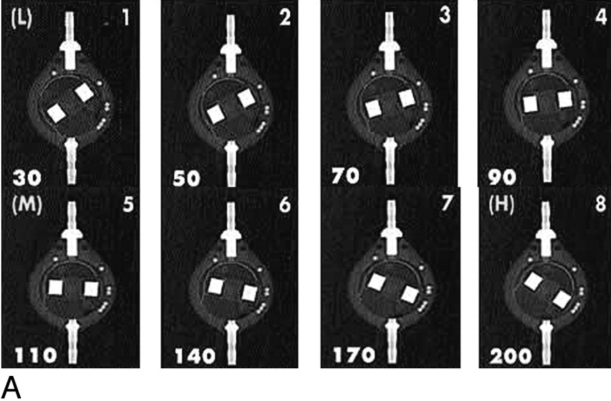
When reading a skull film with this valve in place, you should give the current pressure setting of the valve. This will be a value between 30 mm H2O and 200 mm H2O.
The radiograph should be taken so the valve is seen face-on. This may require the head to be obliqued.
The valve should be on the "up" side of the skull and not against the film.
 Figure 1
Within the valve is a larger (relatively speaking) radio-opaque circle which represents the valve
cam.
There is a small notch in the cam (red arrow in picture 2 below) which moves when the valve is set to a
new pressure setting.
Also contained within the valve is a small radio-opaque dot which is used to indicate the right-hand side
of the valve (blue arrow in Figure 2 below).
Always make sure this is on the right-hand side before reading the pressure (if not flip the film over
because your holding it backwards).
 Figure 2
Once you are oriented, you can compare the position of the notch with the chart to read the pressure setting (figure 3).
 Figure 3

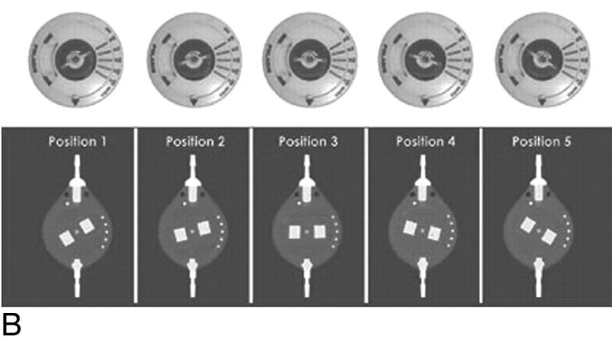
Setting code for the Sophysa Sophy SM8 valve. Operating pressure (millimeters of water) for each position is depicted in the lower left hand corner of each panel.
B. Setting code for the Sophysa Polaris SPV valve. Operating pressures (millimeters of water) for positions 1 through 5 are 30, 70, 110, 150, and 200 mm H2O, respectively.
The setting of the proGAV ® 2.0 valve can be easily identified on post-operative x-rays by placing an x-ray template (supplied) over the radiographic image.

NOTE: The orientation indicator should face three o’clock to maintain the correct position. In the event the image is reversed, simply flip the template over.
A triangle is formed by visually connecting the magnets and drill holes. The sharp corner of the triangle indicates the position of the rotor tip. The direction of the rotor tip indicates the pressure setting of the valve.


ADA Compliance Policy: In accordance with the American with Disabilities Act, Boca Radiology Group strives to ensure that our web site is accessible to individuals with disabilities. If you have any questions or suggestions regarding the accessibility of this site, please contact us via email or call us at 561.391.1728, so we can ensure you receive the information you are seeking.
© 2023 All Rights Reserved